
CNC Busbar Bending Machine: PVC‑Coated Copper Busbar Bending Process Breakdown & Feeding Structure Selection Guide
In high‑low‑voltage switchgear and new‑energy energy‑storage cabinet busbar processing, CNC busbar bending machine serves as core numerical‑control equipment for processing PVC‑mica‑insulated copper busbars and PA12 insulated copper‑aluminum busbars. Different machine models vary greatly in feeding‑structure performance and bending accuracy, directly determining finished‑product qualification rate and production efficiency. This article fully breaks down the full bending workflow of PVC‑coated copper busbars, compares pros & cons of three mainstream domestic feeding mechanisms, explains bending bulge control standards and precision parameters of BL‑TP‑45‑6EL model.
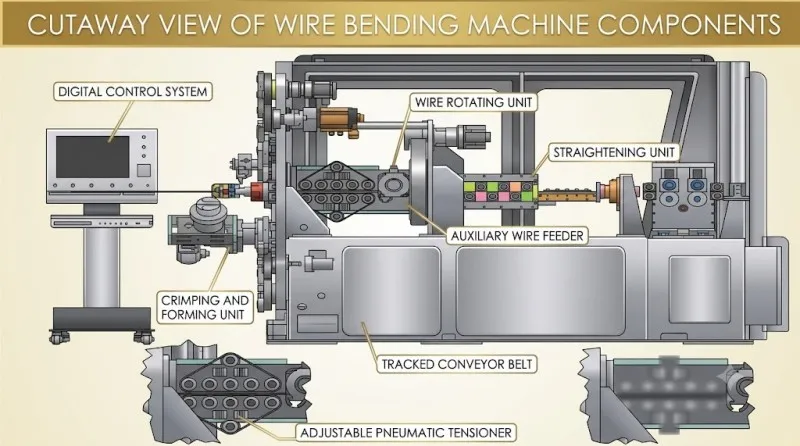
1. Complete Bending Workflow for PVC‑Coated Copper Busbar (Standard Procedure of CNC Busbar Bending Machine)
Supported by automatic control system of CNC busbar bending machine, PVC‑mica copper busbar bending contains six continuous automated procedures without repeated manual adjustment.
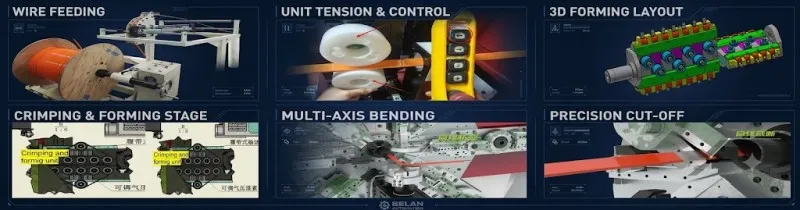
Step 1‑Step 6 Step‑by‑Step Process Analysis
-
Material Loading: Fix coiled PVC‑coated copper busbar steadily on automatic feeding rack and complete reference positioning of incoming material.
-
Pre‑feeding Guidance: Feed raw material into auxiliary feeding unit to regular incoming angle and prevent feeding offset.
-
Roller Straightening: Raw material is pushed into straightening module by auxiliary feeder to eliminate coiling bending stress and guarantee dimensional accuracy of subsequent feeding.
-
Track‑Type Feeding: Straightened busbar is conveyed evenly to bending station via track conveyor, which is the core structural advantage of our machine series.
-
Multi‑arm Coordinated Bending & Forming: 8 groups of servo mechanical arms in bending zone work synchronously to complete flat bending, vertical bending and twist bending according to pre‑set CNC program.
-
Fixed‑Length Cutting & Unloading: After bending is finished, the machine cuts workpiece automatically. Finished busbar drops for collection and one working cycle completes.
The whole closed‑loop automatic process greatly reduces dimensional error caused by manual intervention.
2. Comparison of Three Mainstream Feeding Structures for Domestic Busbar Bending Machines
Domestic manufacturers mainly adopt three feeding schemes for CNC busbar bending machine. Obvious gaps exist in material compatibility, operating cost and processing accuracy.
| Manufacturer & Structure | Advantages | Disadvantages |
|---|---|---|
| Our machine: Track‑type feeding structure | Compatible with PA12 and PVC‑mica insulated copper‑aluminum busbars with strong universality; full‑envelop feeding ensures high precision without scratching material; no need to replace feeding rollers. | |
| Competitor A: 8‑set roller feeding structure | Only fits PA12 copper‑aluminum busbar, incompatible with PVC‑mica insulated material; roller replacement required for different sizes (cost ~4000 USD, replacement time ~20 min); high risk of scratching insulated surface. | |
| Competitor B: Clamping‑type feeding structure | No cutter replacement required. | Mainly applicable for PVC‑mica material; poor compatibility & low efficiency for PA12 copper‑aluminum busbars; slow feeding speed reduces overall productivity. |
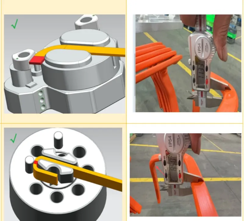
3. Bending Bulge Control Coefficient & Forming Standard for PVC‑Mica Insulated Aluminum Busbar
The most frequent defects of insulated busbar bending include rubber‑layer bulging and mica‑layer cracking & breakdown. The inner bending R‑radius must follow fixed coefficient strictly.
-
Flat Bending Requirement: Inner R‑radius ≥1 × material width. Under this condition, single‑side bulge coefficient reaches 1.6 mm; total bilateral bulge ≤3.2 mm, better than industry upper limit of 4 mm. It effectively protects outer PVC jacket and inner mica insulating layer from tearing.
-
Vertical Bending Requirement: Inner R‑radius ≥1 × material thickness. Single‑side bulge coefficient is 1.5 mm; total bilateral bulge stays within industry standard to eliminate hidden risk of insulation breakdown.
4. Overall Precision Grade of BL‑TP‑45‑6EL CNC Busbar Bending Machine
Dimensional tolerance of this model includes feeding accuracy and bending accuracy, defined by segmented basic processing dimension.
| Tolerance Item | 0‑300 mm | 300‑600 mm | 600‑1000 mm | 1000‑2000 mm |
|---|---|---|---|---|
| Feeding Accuracy | ±0.2 mm | ±0.25 mm | ±0.3 mm | ±0.5 mm |
| Flat‑Bending Accuracy | ±0.1 mm | |||
| Vertical‑Bending Accuracy | ±0.2 mm | |||
| Twist‑Bending Accuracy | ±0.1 mm | |||
Conclusion
When selecting CNC busbar bending machine for multi‑material insulated busbar processing, prioritize track‑type feeding mechanism, controllable bending‑bulge coefficient and segmented dimensional tolerance. It broadens material processing range, lowers long‑term production loss and maintenance cost, and fits mass‑production demand of busbars for new‑energy and high‑low‑voltage electrical industries.
Belan Machinery provides professional wire‑forming solutions for automotive industry. If you are comparing busbar‑processing equipment and want to get detailed specification, sample‑processing video and customized quotation of BL‑TP‑45‑6EL, welcome to consult our technical‑sales team online. We will deliver customized machine solution according to your material property and capacity target.
 +86-18098256570
  Email
Email

